In this comprehensive guide, we show you how to professionally install a split charge wiring loom into a VW T5/T6 camper van.We explain how to route wiring,.. The B2B charger wiring diagram shown below, is similar to that of a split charge relay. The positives of the starter and leisure batteries are connected through the split charge relay - ensure a fuse (normally 100A, though can vary) is installed on each side.

5m MVM Split Charge Relay Kit Ready Made megavanmats
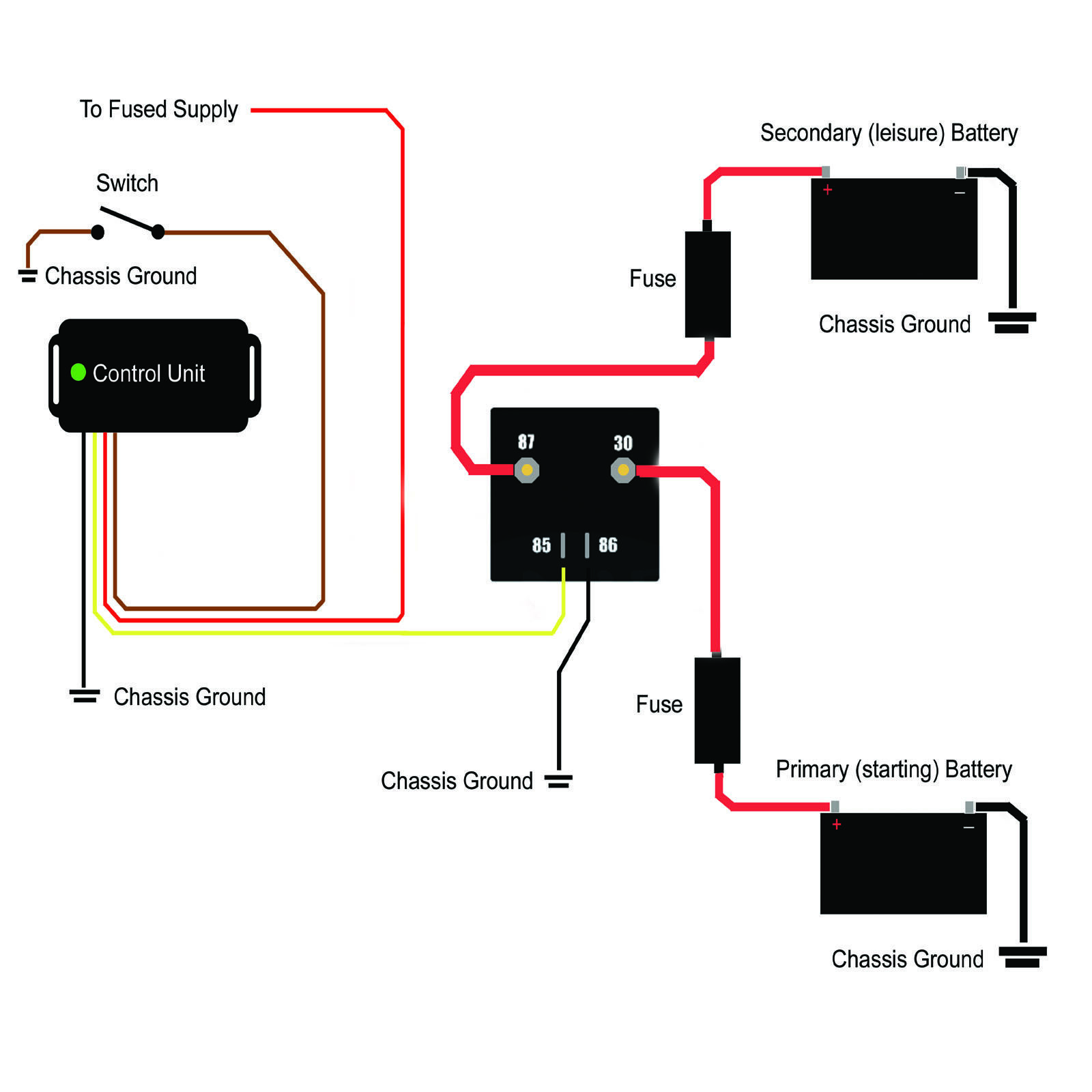
Voltage Sensing Split Charge Relay Wiring Diagram Organicid
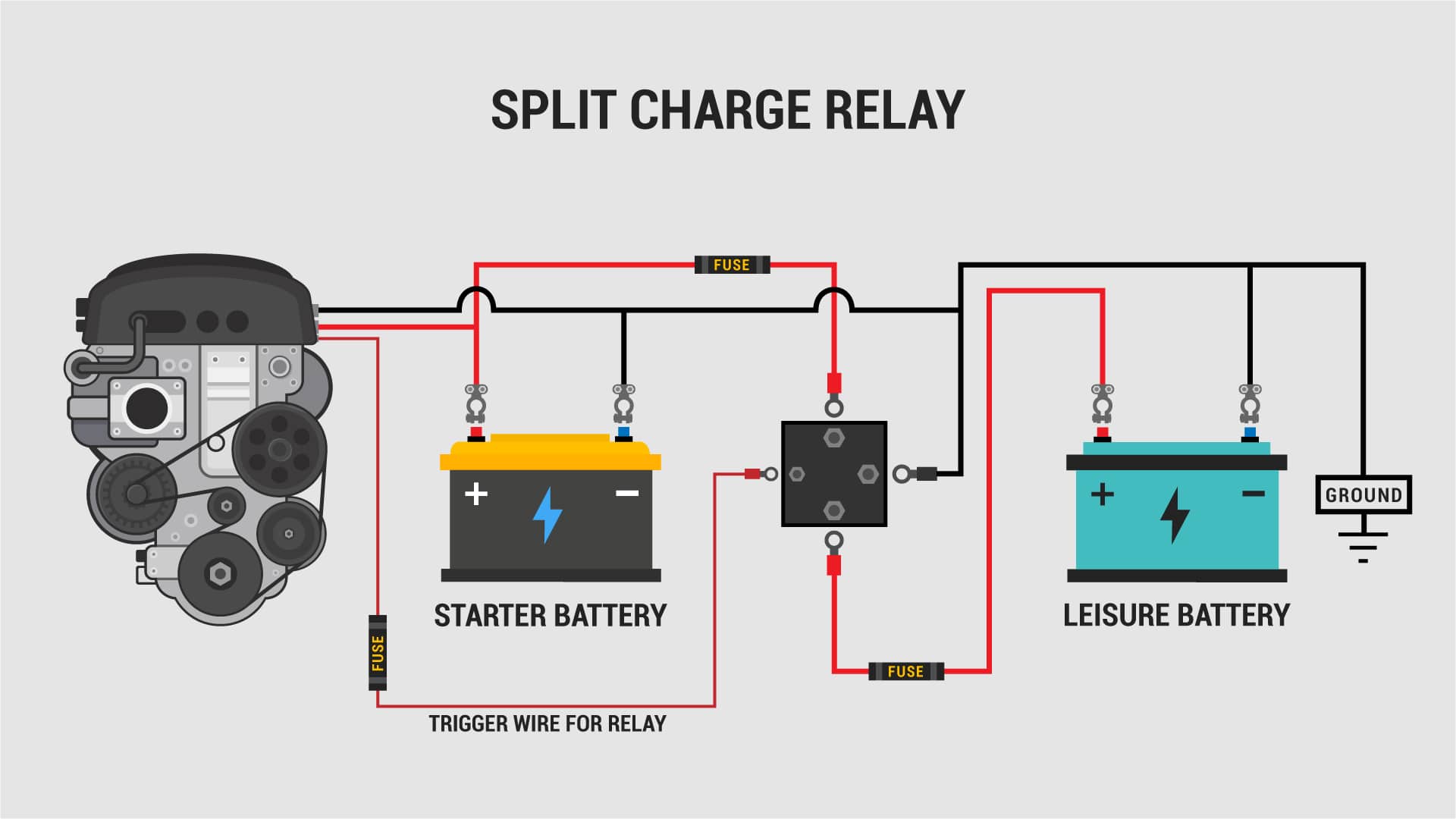
Durite Split Charge Wiring Diagram Wiring Diagram and Schematic

Split charge relay wiring VW California Owners Club

Buy Riiai Split Charge Relay kit,Dual Battery Isolator,12V 140A Power Voltage Sensitive Split
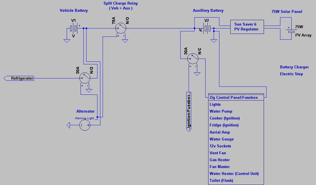
Split Charge Relay Wiring Diagram 5m Ready Made Split Charge Relay Kit 12v 140 Amp Vsr 110a
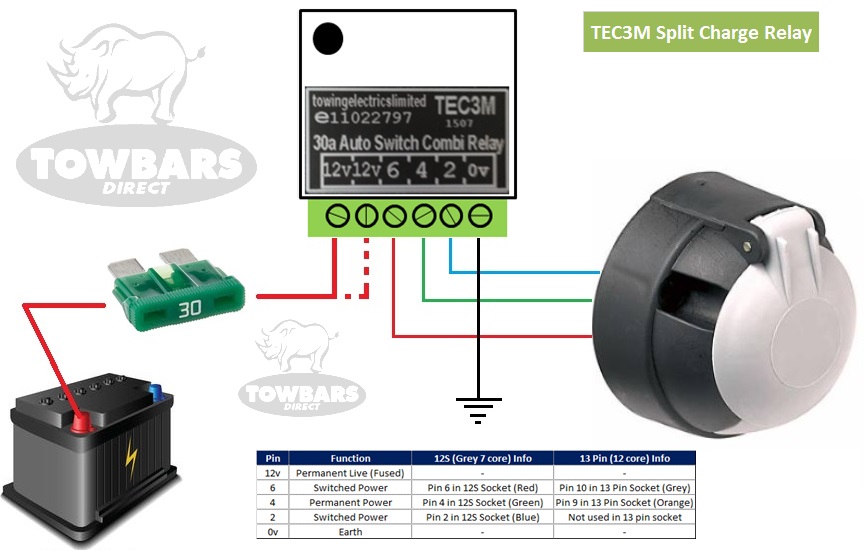
Self Switching Smart Relay for 12S / 13 Pin Towbar Wiring Charging Fridge TEC3M eBay
Volt Relay Wiring Diagrams Durite Vsr Split Charge Relays V thechillicystreets

Tec3m Split Charge Relay Wiring Diagram Wiring Diagram
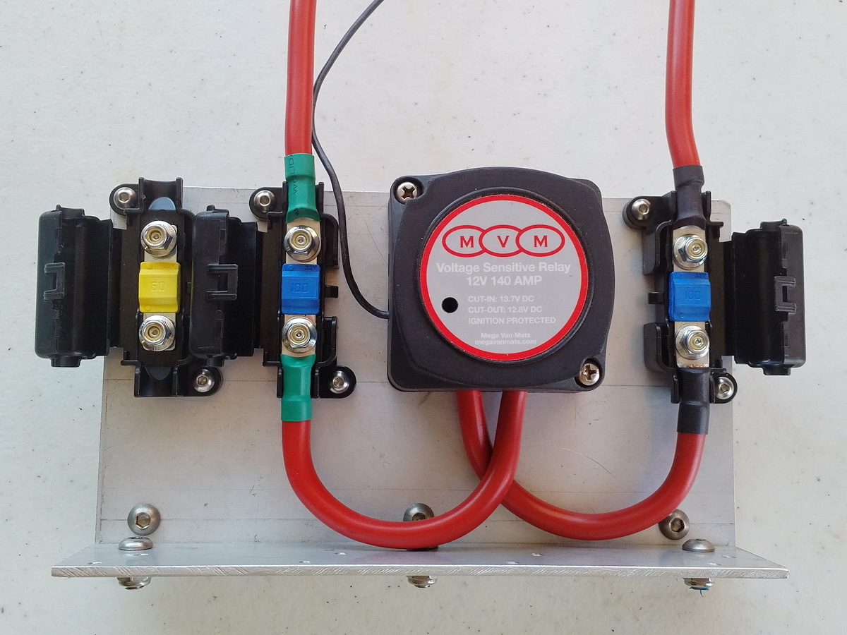
Split Charging Relay Wiring Diagram Wiring Diagram
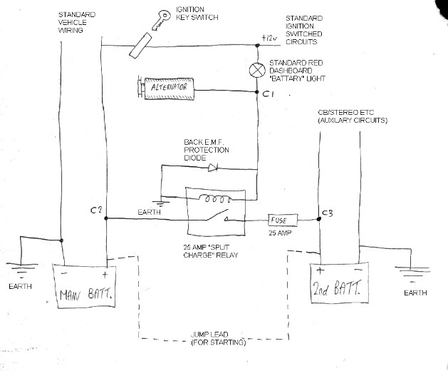
Split Charge Relay Wiring Diagram 5m Ready Made Split Charge Relay Kit 12v 140 Amp Vsr 110a
Leisure Battery Relay Wiring Diagram eternalinspire

Split Charge Relay schematic

Split Charge Relay Wiring Diagram split charge relay wiring diagram Wiring Diagram / Usually
Durite Relay Wiring Diagram

Hella Split Charge Relay Wiring Diagram Ian Drompal
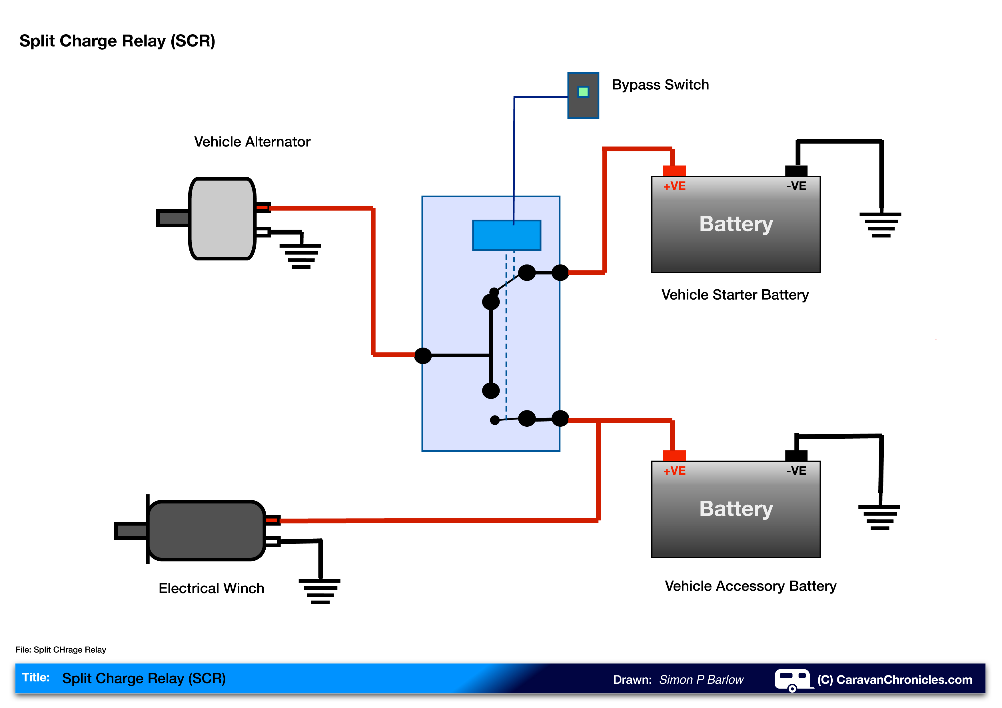
Vsr Split Charge Wiring Diagram Styleced

Volt Relay Wiring Diagrams Durite Vsr Split Charge Relays V thechillicystreets
Relay Wiring Diagram Greenful
-3864-p.jpg?strip=all)
maypole split charge relay wiring diagram Schema Digital
A split charge relay wiring diagram is a visual representation of the circuitry of an electrical system. It shows the different components of the system and how they should be connected. This diagram can help electricians and homeowners alike in understanding how to correctly set up their electrical system. It is also useful in troubleshooting.. Hold it in position and mark the top locating hole. Drill this hole for the relay, and then mount the unit using a suitable self-tapping screw to ensure it's properly secured. To save time, we usually use cable ties to fix the new wiring loom to the existing wires for the rear lights in the T2.